

CONSTRUCTION
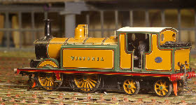
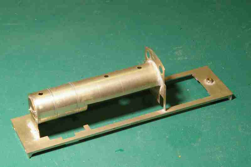 Before progressing much further, the body has to be at a stage for a trial fit on the chassis to check for clearances. The photo shows a fairly typical stage, with the running plate, boiler and cab partly complete. In this case the boiler has been partly cut away, and this will all be covered in by the side tanks at a later stage.
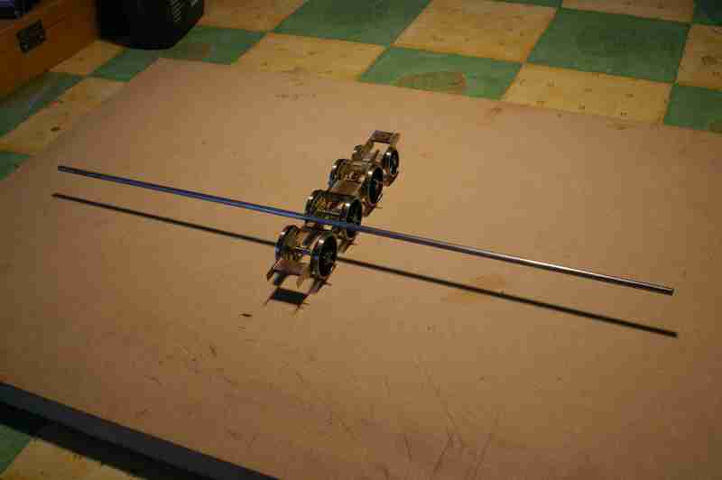
 The compensation beams can now be fitted, and in this case because centre coupled axle is the driven axle, I have used side beams (18th nickel silver) on the front two axles, and a single central beam between the rear coupled axle and the radial axle box. The photo shows the leading axles with a temporary metal rod across the frames holding the beams in place. This
  will be replaced by two separate pins soldered to the frames. The central beam is carried by a perspex rod between the frames -
 The chassis is now ready for first assembly and fitting to the body. Before assembly I make sure that the bearings and axles are a good running fit. The bearings are given a final touch up with a reamer, and the axles are polished, by fitting them into an electric drill or lathe and applying some very fine emery (600 or 1200 grit) with a little oil. Polishing the axles can make a significant difference to reducing overall friction. At this stage, the chassis should roll freely down a gentle incline.
It’s obviously important to get the wheels square to the axles, and a lathe can be used for this (fit the wheel into a three jaw chuck, support the centre with a back stop, and use the tail stock to push the axle home). There are now several commercial alternatives for this, the best of which I think is the GW models jig.
 I find the compensation beams often need a little adjustment to get the chassis height correct (regardless of how much care I take to get it right in the first place). Measuring the chassis height at each end is easy enough, and a bit of judicious filing or bending of components will fix the problem. Checking that the chassis is vertical (so that the body will be upright) is a bit more difficult -
 Finally the body outline can be added, and clearances checked to make sure that there are no tight spots. At this stage I quite often add a few bits of insulation tape where the chassis and body touch, and check that the two are insulated from each other. This obviously has to be repeated as the rest of the body is completed, but at least with the body only part complete, it’s a lot easier to see where problems might arise.